Battery Box Transcript
This is the transcript for the video Building A Battery Box For a DIY Lithium Battery. For a more detailed writeup on the same process, visit our full writeup: Constructing A Battery Box.
Hi Everyone! This is Lexi from Roam Lab and today we are building a box for our DIY lithium battery. It is a complicated project, so buckle in!
We have 16 3.2-volt lithium battery cells, which we are assembling to make two 24-volt batteries. Each battery will need a box to securely house and protect eight battery cells, a battery management system, wires, and other electrical connections.
While we could buy a battery box, we want to create something that will pay tribute to our truck camper build and show off the interior workings of the battery. For us, that means a two-part design with a riveted aluminum base and a plexiglass cover. The result is a rather unorthodox battery box. But, here, let me show you.
We are starting with the aluminum base of the battery box. Each edge on the bottom is supported by a bar of extruded aluminum. The two lengthwise bars are T-bars. These sturdy 1/8-inch thick bars support the battery cells inside the box and connect the box bottom with another leg connecting the box side, and the outer leg serving as a mount point to the camper. These corner bars are secured to the box walls by rivets spaced one inch apart. We mark and prep each hole with a hammerless punch before drilling 1/8” holes for the rivets.
We are using scrap anodized sheet aluminum for the walls of the box. Not only is this a fun call-out to the aluminum work we have been doing on the camper, but it will allow the battery box walls to flex to make space for the battery cells without relying on a hinge mechanism.
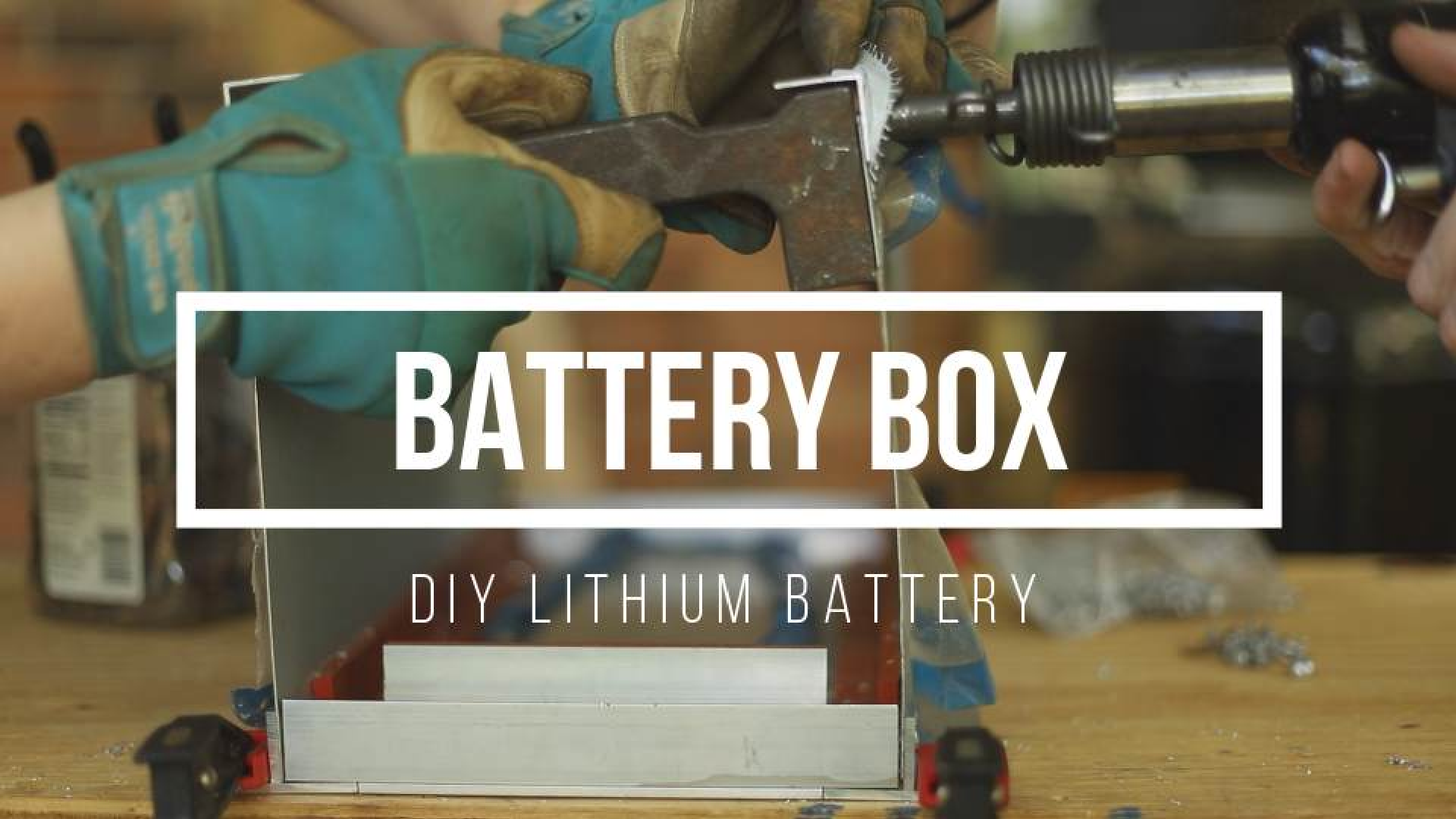
The goal of this box is to make a container that has a snug fit for the batteries. We want to keep them from moving around too much while protecting them from anything that might fall on the batteries or jarring impacts. There is little room for mistake, so I measure each piece multiple times before cutting or drilling. We use clecos to secure the aluminum sheet walls to the extruded edge bars. These are standard riveting tools for fast, secure, but temporary connections. Once the holes are secured with clecos, we permanently fasten the sheet aluminum wall to the extruded edge bars with a buck rivet. This is a two-person job involving a riveter and a bucker.
The riveter uses a pneumatic rivet gun fitted with the appropriate rivet set to hammer the rivet head on one side of the aluminum that we want to fasten. In this case, we are using brasier head rivets, so we want a brasier head rivet set. On the other side of our project is the bucker, who uses a flat metal surface known as a bucking bar to create a flat hard surface perpendicular to the shaft of the rivet. Every time the rivet gun hits the head of the rivet, the shaft flattens against the bucking bar to gradually fasten the pieces of aluminum together.
While the rivets are almost flush with the aluminum sides, those bumps could do some wear and tear on the battery cells over the years. So, I cover the riveted seam with a silicone rubber strip. Not only does this hard rubber protect the battery cells from the flattened rivet shafts, but it will also allow a degree of flexibility in the fit of the box so that the cells can be snuggly and firmly secured in the box. As a final bonus, this will help with the shock resistance of the battery while we tackle rough trails on our off-road adventures.
Next up, the bottom of the battery box is also made of more sheet aluminum scraps. We’ll follow the same process as the box walls: prepping, drilling, and riveting holes to connect the bottom sheet aluminum to the extruded aluminum edge bars. This time, it’s a little more awkward to do as the sidewall that we riveted earlier gets in the way. Even so, we make quick work of this connection.
Attaching the edge extrusion and aluminum sheet for the next wall requires particular attention to detail. We want the two walls to be close enough to firmly wedge in battery cells to minimize any shifting while the cells are in the battery box. So, we take two of the cells to represent the set and clamp them in position at the far ends of the battery box while we drill and cleco the central edge for the box’s sidewall and bottom.
Before moving on to rivet, we are going to add supports for the narrow sides of the box base. These won’t be thick extrusions connected to aluminum walls like the long sides. Instead, they are more lightweight right-angle-bars that will act as mount points for the plexiglass cover as well as one final T-bar that will divide and secure the batter cell section from the battery management system or BMS.
We start with the T-bar divider. Its base is three inches wide, creating a dedicated one-and-a-half-inch deep area for the BMS. Once one side of the T-bar divider is clecoed to the battery box bottom, we move on to prepping the right-angle-bar, which will attach to the other end of the T-bar divider and will secure the plexiglass cover. We repeat the same process for the right-angle-bar for the other side, without the complication of another T-bar divider. This will only be riveted to the battery box bottom and the two corner extrusions.
With all these edges clecoed in place, it’s time to rivet the final battery box bottom pieces together. Like the side rivets, we cover these rivet lines with silicon rubber strips.
And now, we are ready to move onto the final section of the battery box base: the top edge bars. Like the bottom edge bars, these secure the battery cells into the battery base. Unlike the bottom edge T-bars, these are simple extruded aluminum right-edge bars with one side connected to the battery wall and the other side hugging the battery cells in place.
These have shorter arms than the bottom edge-bars. This is because we want them long enough to secure the battery cells and keep them from falling out of the box, but not so long that the aluminum bar might hit the battery cell terminals. The battery cells will be arranged in series, and aluminum is a highly conductive metal. So a bar that crosses all the terminals on one side will create a short. Thus, the short arm length, as well as some silicon rubber, are important considerations to prevent any surprises
Like all the other edge-extrusions, we are drilling rivet holes one inch apart and then clecoing them to the top of each batter box wall. This is also meant to be a snug fit, so we have two battery cells in place to ensure a perfect fit while being careful not to let the drill bit get too close to the cells.
This is the most straight forward riveting we have in this project since both sides are easy to access. This is a fun opportunity to demonstrate riveting and bucking at the same time. We set up the camera perpendicular to the battery box wall, and you can now see the rivet gun and bucking bar in action. We can finish off the battery box base by adding the final silicon rubber strips and then peal off the protective plastic that has been keeping the aluminum walls scratch free throughout this build project.
As satisfying as this is, we still have other pieces of the battery box to complete. The current box base will secure the battery cells from the top, bottom, and sides, but we need something else to squeeze the batteries together. For this, we will have two sets of aluminum bars for the exposed sides of the battery cells that will be connected using threaded rods and a hex nut on each side. Tightening the hex nuts will squeeze the batteries in-between the aluminum bars to minimize any shifting.
These bars will do double duty: one set is also the mount point for the battery management system. The BMS already has a hole on each corner of the circuit board for mounting, so we will use these holes to secure the board to the aluminum bars. First, we drill holes in the bars the match the distance between the holes on the circuit board. Then we thread these holes with an M5 tap so that they will accept bolts. It’s a little awkward to start. But once the hole is threaded, we can now insert some threaded rod and test out the mount on our BMS. Like everything else that will be in direct contact with the battery cells, we go ahead and add some padding with the silicon rubber strip.
Next up, we are going to need a bus bar that connects the positive and negative terminals outside of the battery box to the battery cells inside of the battery box. Unlike the bus bars we made in a past video to connect the battery cells, these bus bars will have a U-shape. Thus they can be flat where they are bolted onto the battery cell and the external terminal but also travel vertically to allow for the distance between the cell and the terminal. We accomplish this U-shape with a vice, a metal bending tool, and a rubber mallet.
With the U-shape complete, we can cut off the excess copper bar.
Next, we need to make holes for the bolts that will connect the bus bar to the battery cells and the outside terminals. Drilling the aluminum rivet holes has been simple, but these holes are very large, and the bigger the drill bits we use, the more friction and heat we encounter. So we gradually increase the drill bit size until the holes are large enough to accept the bolts. The hole for the outside terminal is particularly large and requires one of our largest drill bits. We drilled two holes on each side to allow for a bit of wiggle room when fitting the bolts before tightening them. When we are done drilling, we file between the two holes to create a single, oblong hole.
Finally, it’s time to make the plexiglass cover. For this, we are cutting a sheet of 1/8” acrylic. We are using a circular saw blade designed for cutting acrylic to minimize the amount of heat created when cutting the acrylic. This cuts back on any melting or burring along the plexiglass edges.
For the top section of the plexiglass cover, we drill two holes for the positive and negative terminals. These are so large that we use a one-and-a-half-inch circle drill bit. The heat from this process is enough that we use a deburring tool to clean away pieces of melted acrylic and then test the fit of the terminals.
Now, it’s time to connect the pieces of the plexiglass cover. We pull away from the protective plastic from the area we are working with. Rather than riveting, this part of the battery box will be bound with an acrylic solvent in an applicator bottle with a needle tip. This is a delicate process where we let gravity do most of the work. It only takes a little bit of the solvent to weld the edges of the plexiglass together. The goal is to maximize the surface area bound by the solvent while not over applying, which could result in clouding along portions of acrylic and is unintentionally exposed to the solvent.
Once the plexiglass cover has been allowed to sit for a day so that the connections can fully cure, we can go ahead and but the whole box together.
Keep an eye out for the full step by step assembly of our DIY lithium battery in our next video.
You can find more details with pictures on our website, roamlab.com. If you found this helpful, please give it a like. And subscribe to Roam Lab for future diy projects.